Two circuits, one handover
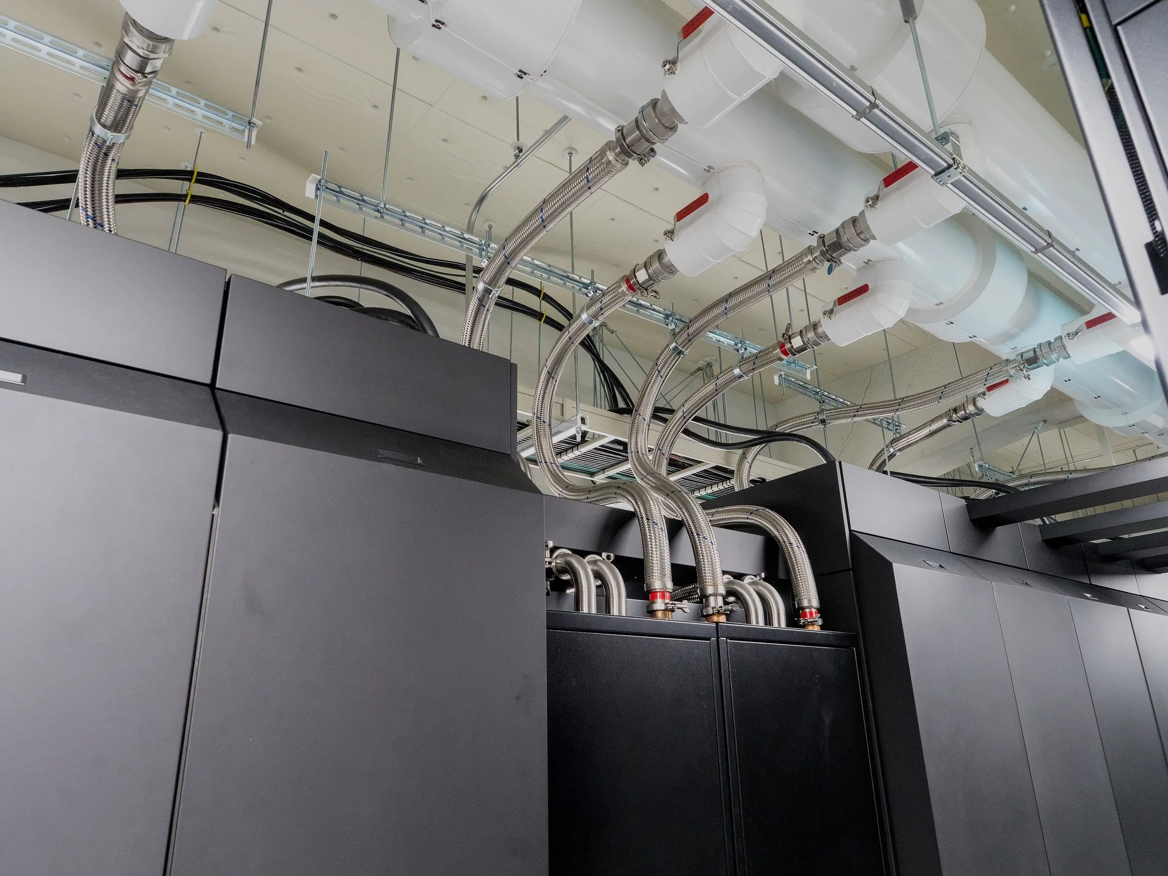
Follow a warm pipe away from a liquid-cooled server and it soon reaches a point where the heat has to pass to another system. In a common liquid-to-liquid arrangement, that handover happens inside a coolant distribution unit, or CDU. The two fluids never mix.
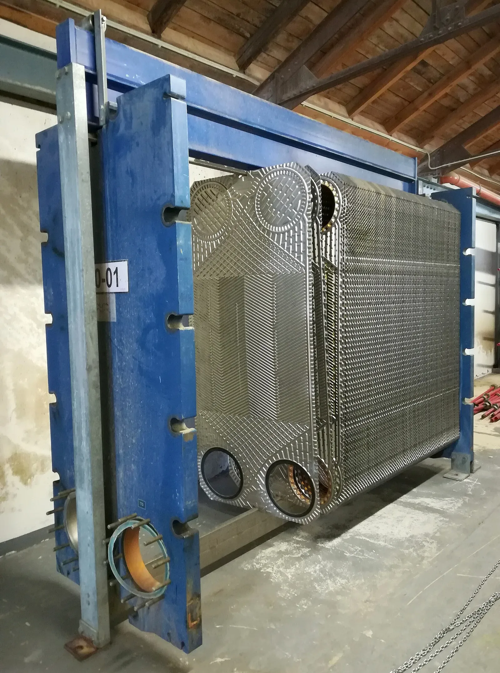
A heat exchanger separates the building’s facility-water circuit from the technology cooling circuit that serves the IT equipment. Heat crosses the exchanger’s surfaces while each fluid stays in its own passages. That boundary lets the CDU deliver coolant at the temperature, pressure and chemistry the IT equipment needs.
Colder is not automatically better. Keeping exposed cooling surfaces above the dew point of the surrounding air helps avoid condensation, one more reason the temperature is controlled rather than simply driven down.
Visual guide
Where the two circuits meet
Choose a step, or select a part of the diagram.
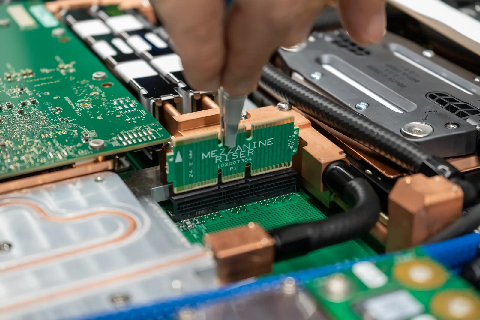
- Warm from the chips. Coolant runs through cold plates on the chips in a rack. Its warm return, 40 °C in the magazine’s worked example, flows into the CDU’s heat exchanger.
- Two passages, one wall. Inside the exchanger the two flows run in opposite directions in their own passages, divided by a wall. The two fluids never mix.
- Warmer to cooler. Heat crosses the wall from the warmer technology side to the cooler facility side. In the worked example the technology side is warmer at both ends: 40 against 35 °C at one end, 30 against 25 °C at the other.
- Back to the plates. In the worked example, the coolant leaves the exchanger at 30 °C, and a pump inside the CDU pushes it back to the cold plates.
- Facility water. In the worked example, facility water enters the exchanger at 25 °C and leaves at 35 °C for the building plant. It may carry the heat on to a chiller, an outdoor cooler, a cooling tower or a heating load.
Pumps, filters and controls
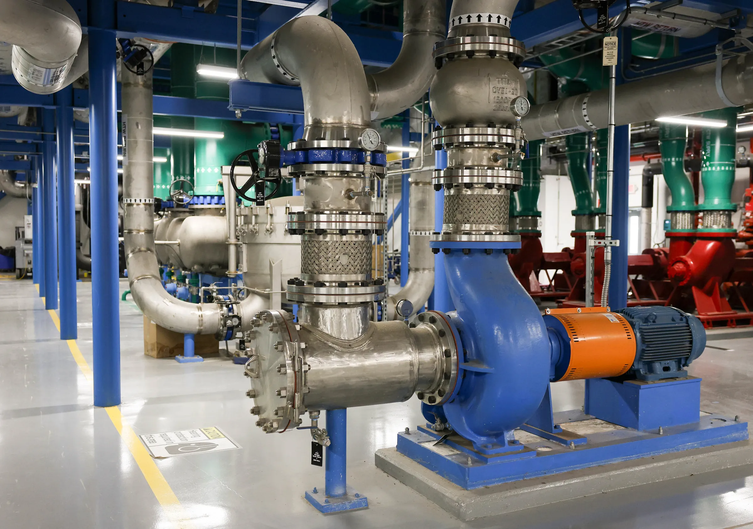
The exchanger is only part of the unit. Depending on the design, pumps circulate the coolant, filters protect the circuit and controls manage flow and temperature. Instruments let operators see what the circuit is doing. A CDU inside one rack and a larger unit serving several racks do the same broad job at very different scales.
Some units hand the heat to room air instead of facility water. Vertiv describes liquid-to-air CDUs as a practical retrofit path for rooms that already rely on air cooling, but that air system then has to carry the extra heat. The heat moves to a different system; none of it disappears.
Beyond the cabinet
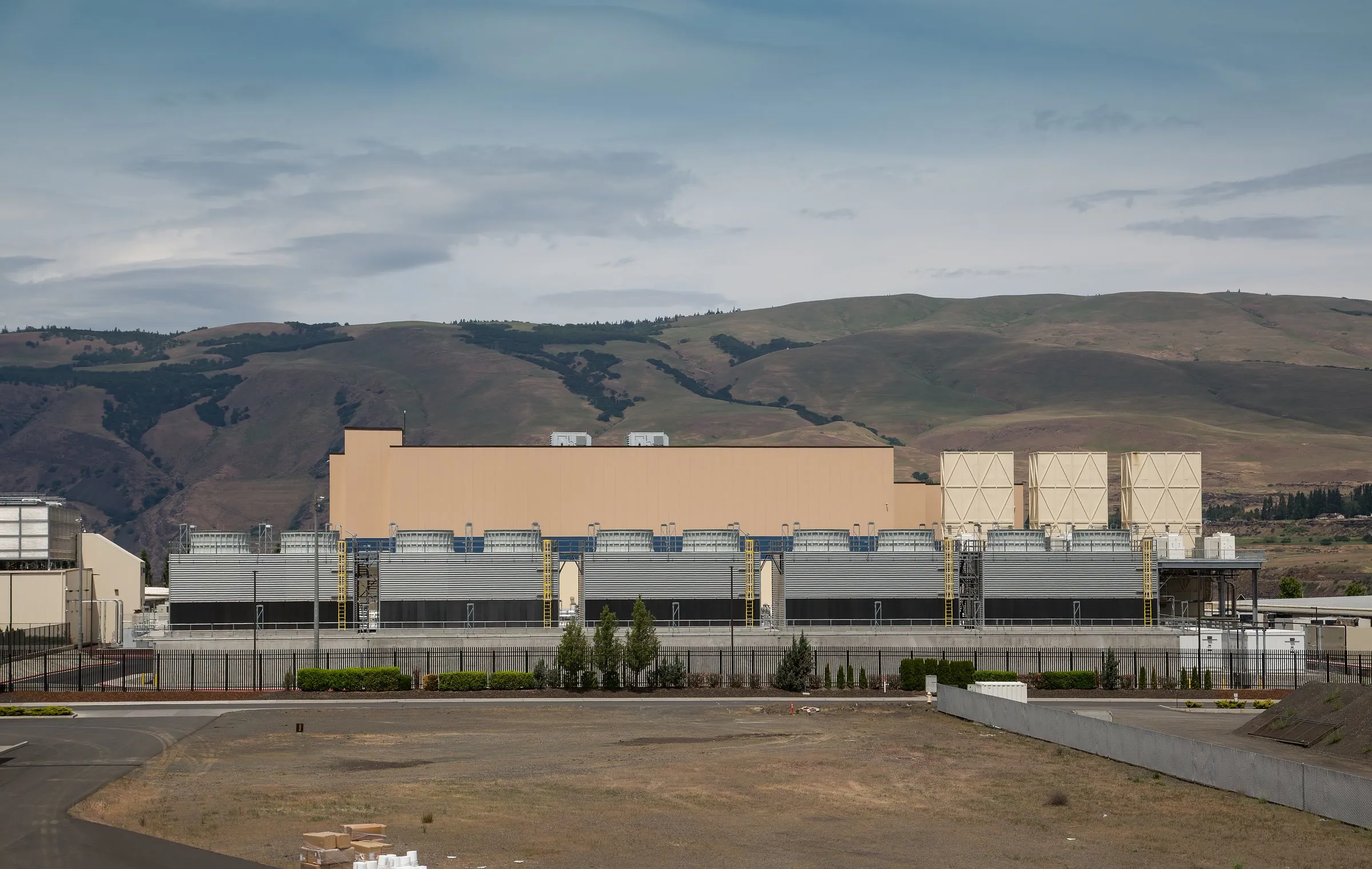
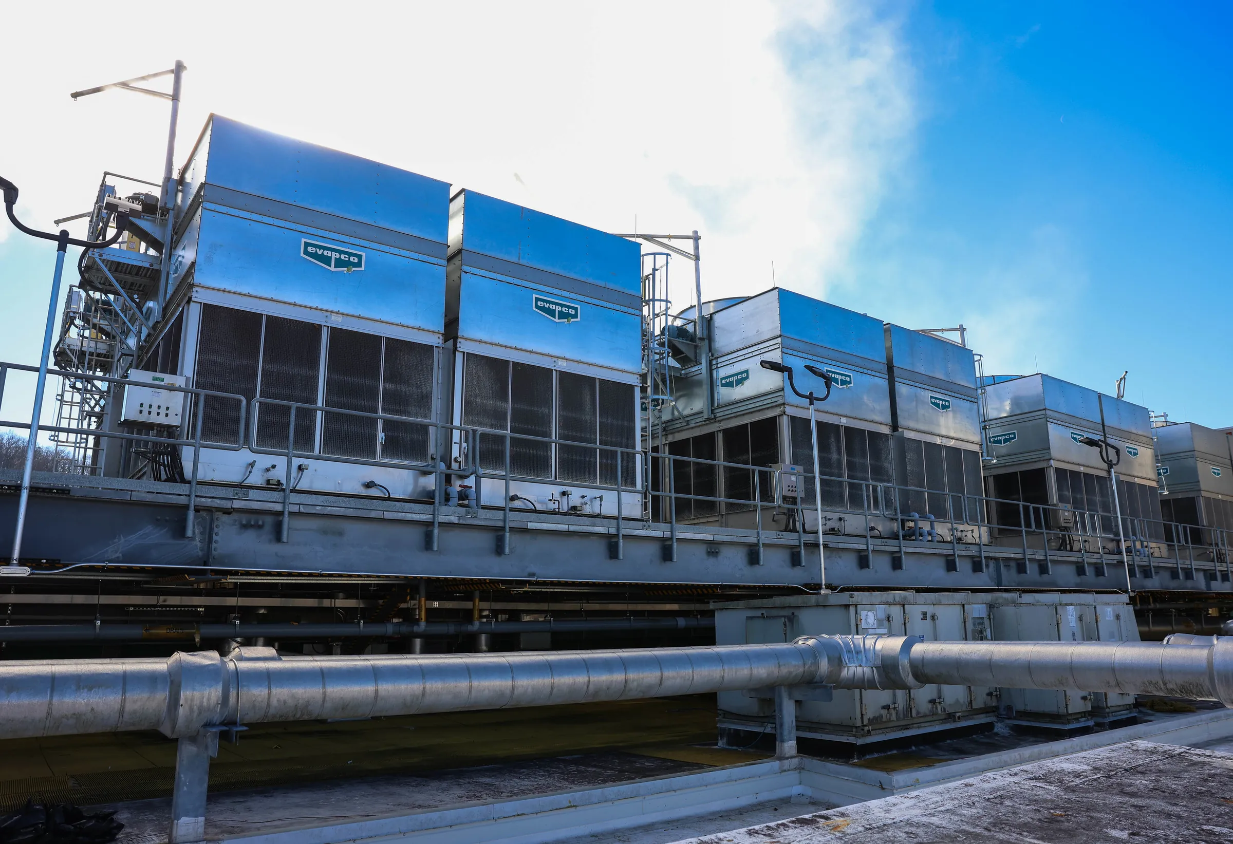
After the CDU, the heat may travel on to a chiller, an outdoor cooler, a cooling tower or a heating load that can use it. The US Department of Energy’s design guide treats liquid cooling as one link in this larger chain.
So a cooling-capacity figure needs context: the temperature difference available, the flow, and the operating limits of the equipment on both sides. A large rating on the CDU cannot make up for a building circuit that cannot accept the heat. The design work is in matching the two, so that heat has a continuous route from the chip to somewhere that can take it.
Sources
- Data Centers and Telecommunication Facilities, Chapter 20ASHRAE Handbook · 2023
- Deploying Liquid Cooling in Data Centers: Installing and Managing Coolant Distribution UnitsVertiv · 15 March 2024
- Best Practices Guide for Energy-Efficient Data Center DesignUS Department of Energy · July 2024
Company sources describe their own work and terminology. Our editorial approach