Follow the heat
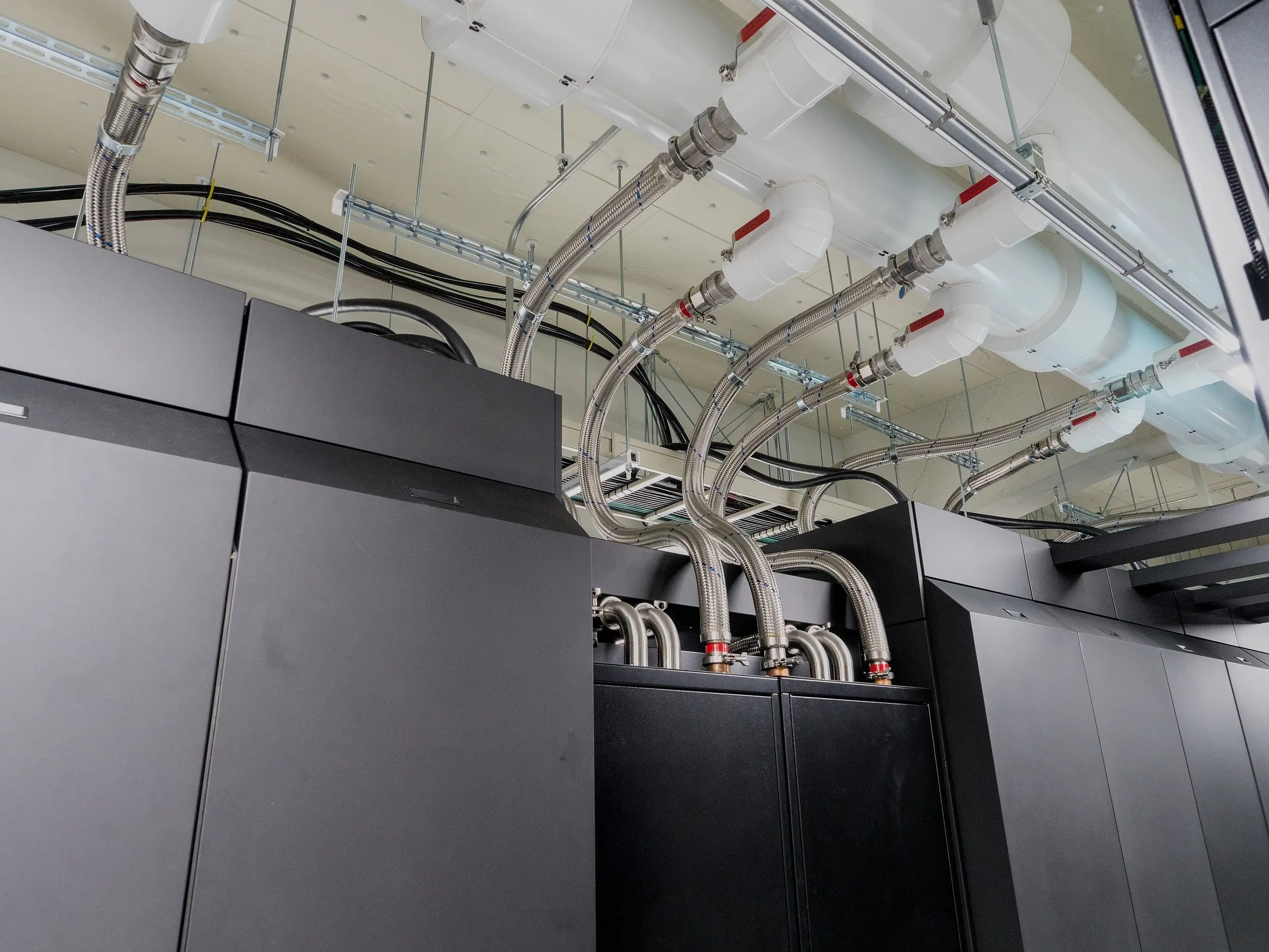
A closed loop is reassuring to look at. The pipe returns to where it began, and the water seems to have nowhere to go. The question is how the heat leaves.
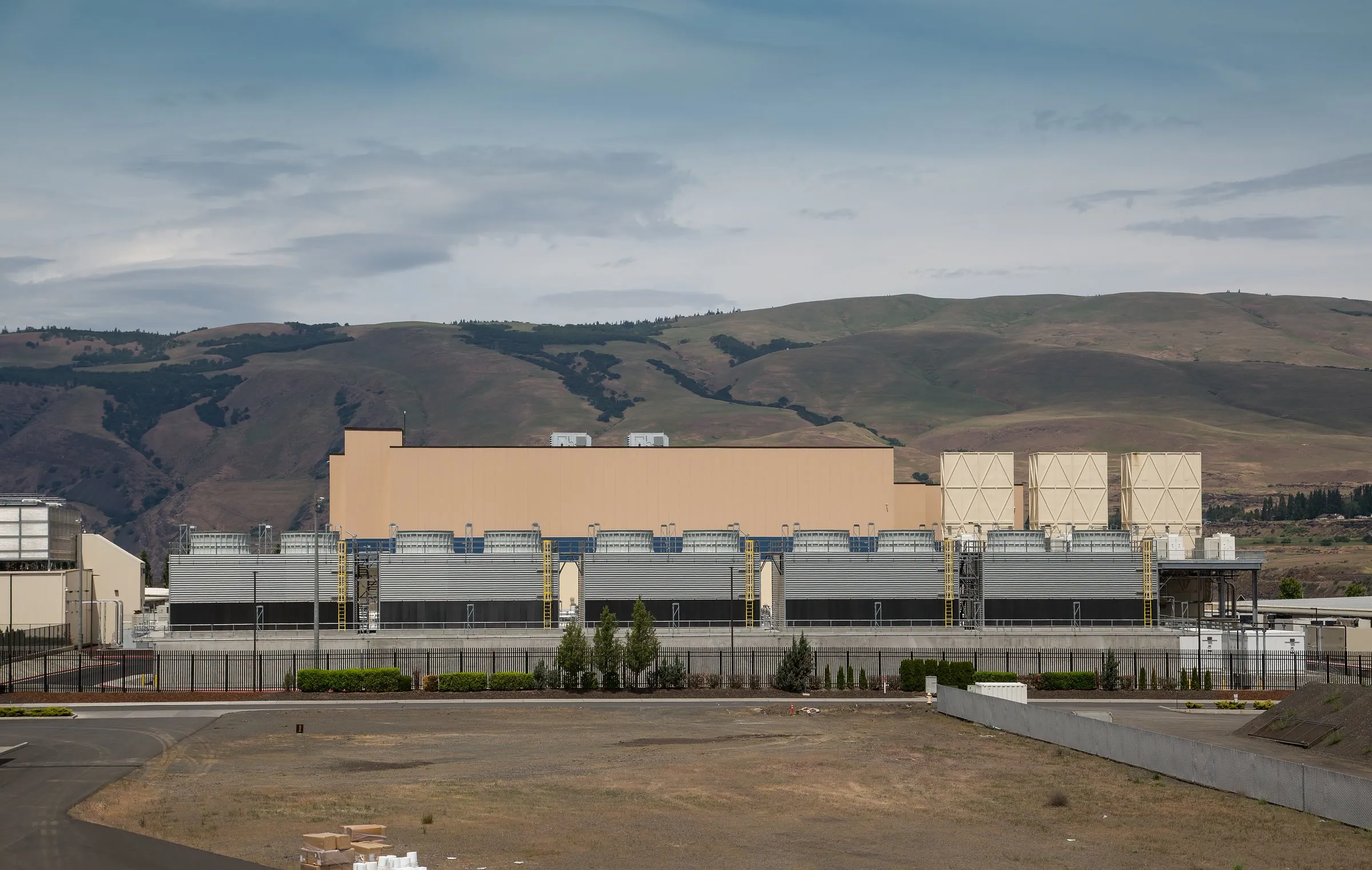
A recirculating server-cooling loop can hand its heat to another circuit, and farther along that chain a cooling tower may reject it by evaporating water. The US Department of Energy illustrates this arrangement in its guidance on cooling-water efficiency. The server loop is closed, and the site still consumes water.
Visual guide
Where the heat and the water go
Choose a step, or select a part of the diagram.
- Closed server loop. In both routes a closed server loop carries warmer water from the servers to a heat exchanger and back. Only the heat crosses into a second loop; the water stays in the loop.
- Cooling tower. In route 1 the second loop is open to the air at a cooling tower. Vapour carries most of the heat away, a little water leaves as drift, blowdown is drained and make-up water replaces the losses.
- An upper bound. If all the heat left by evaporation, about 1.5 m³ of water would evaporate per hour for each megawatt of heat. Real towers also shed some heat as warm air, so this is a calculated upper bound.
- Dry cooler. In route 2 a closed facility loop takes the heat to a dry cooler. Its fans push the heat into the outdoor air as warm air, with no vapour and no blowdown.
- The trade-off. With the dry cooler, no water evaporates at the site for cooling. But it needs outdoor air cooler than the water, and generating its fan electricity can use water elsewhere.
A narrower claim
Some designs avoid evaporation. In December 2024, Microsoft described a chip-level cooling design in which water recirculates between servers and chillers, with the stated aim of eliminating water evaporation for cooling. The company separated that claim from water used in kitchens and restrooms.
Microsoft said replacing evaporative systems with mechanical cooling would raise its PUE, and described the result as a nominal increase in annual energy use.
The post also said the existing fleet would still use a mix of air-cooled and water-cooled systems. New sites in Phoenix, Arizona, and Mt. Pleasant, Wisconsin, were to pilot the design in 2026 and begin coming online in late 2027.
The second water meter
Some water use sits outside the site boundary. Electricity generation and semiconductor production also use water, and the IEA’s Energy and AI report counts these indirect demands separately from water used directly at data centers. Shifting cooling from water to electricity can move part of the impact elsewhere.
Place and season also matter. A litre consumed in a water-stressed catchment during a hot, dry month weighs more locally than the same litre elsewhere, and a low annual figure can hide that pressure.
The useful picture has three layers: water circulating inside equipment, water consumed at the site, and water tied to the wider supply chain.
Sources
- Cooling Water Efficiency Opportunities for Federal Data CentersUS Department of Energy · Accessed 23 October 2026
- Sustainable by design: Next-generation datacenters consume zero water for coolingMicrosoft · 9 December 2024
- Energy and AIInternational Energy Agency · April 2025
Company sources describe their own work and terminology. Our editorial approach